How do you make a helical gear in AutoCAD 2d. This free highly functional gear drawing software allows you to easily create gear drawings by entering various parameters hub shapes hole dimensions keyway dimensions and other information.
Bevel Gear Autocad 3d Modelling Rendering Autocad Forums
Anyway some how I got into drawing on this plane.

. Trim down the circles. And since these graphs are polylines they can be extruded and used to generate AutoCADGStarCAD. Various types of gears such as spur gears bevel gears rack gears worms and internal gears can be drawn and the drawings can be output as DXF files.
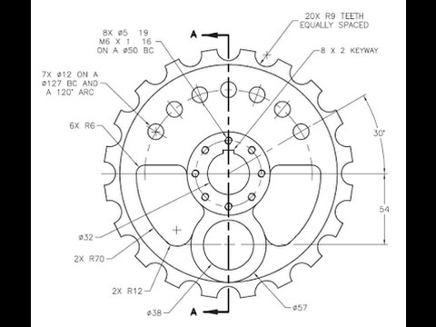
Here is the Dimensions. It is a model design that helps one to Practice 2D Commands Easily. CAD lessons CAD CAE CAM.
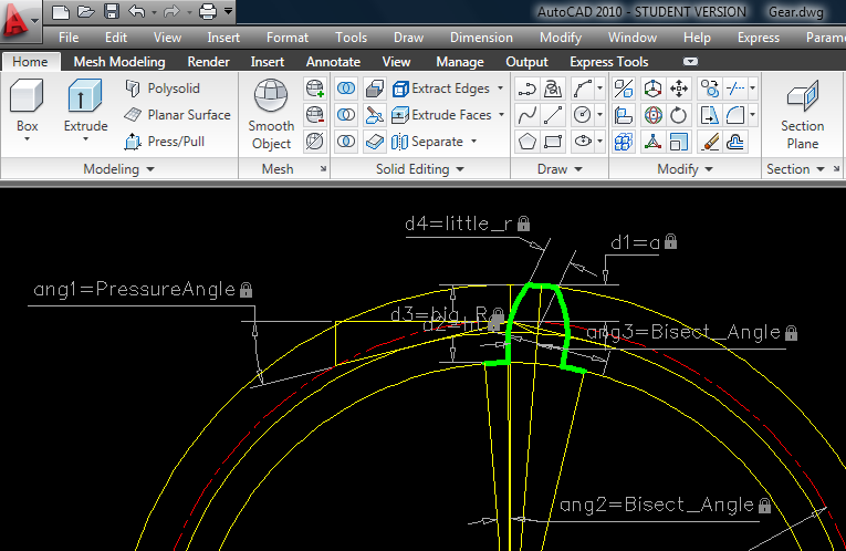
I enter the formulas and the parameters and we get the involute profile of a spur gear. Calculate the pitch centre distance. When the GEAR1 command is called the program requests gear center external diameter number of teeth and angle of pressure then the calculated module or pitch according to the units of the drawing.
Up to 7 cash back 2D drafting and drawing is the process of creating and editing technical drawings as well as annotating designsDrafters use computer-aided design CAD software to develop floor plans building permit drawings building inspection plans and landscaping layouts. I find it much easier than using the conventional method. Turned off the UCS icon.
I only want to draw in the 2D or xy coordinates. I have details on a gear but I never drew one before. Students Teachers Practitioners Educator Students Experts Learners etc.
Make two arcs like this one for cutting teeth. You can download an autocad lisp file called Truegear from wwwcadforumcz. Then click on the Helix command as in the red box.
Draw a vertical centre line for the driver gear on the left. In the Select Part Size dialog box select the size of the chain. And our calculation parameters are as follows.
The trick is to simply draw a circle with the desired radius in this case big_R or r2675 with the center at a location that you do know. SIMPLE GEAR in 2D with Dimensions. Select the Library button.
With it you can draw almost all types of gears both 2D and 3D. AutoCAD AutoCAD Architecture Compass Inventor Revit 3ds Max. In the Number of Teeth to Draw field enter the number of teeth for the sprocket in order to calculate the diameter of the pitch circle.
Start by drawing a horizontal centre line for both gears. Make a circle of 35mm radius at center. Works on the Autodesk AutoCAD platform.
Drawing meshing gears Step 1. To draw spirals in Autocad click on the Draw pop-up menu as shown by the red arrow above. C1 70477 base diameter 2.
Make another circle of 50mm concentric to previous one. Measure the centre of the driven gear from the centre of the driver gear. Hello I may not be able to explain this correctly but let me try.
Can I get help. Drawing in 2D. I have been using autocad LT for many years.
The user can modify it which can change the external diameter. Developed in the language AutoLISP useful for research as it gives freedom in most of its parameters and manufacturing by means of specialized machines in the metal cutting. Measure the centre of the driven gear from the centre of the driver gear.
Start by drawing a horizontal centre line for both gears. The Computer-Aided Design CAD files and all associated content posted to this website are created uploaded managed and owned by third-party users. Draw spur gears paying attention to the involute profile of the teeth based on the equations of the magazine TECH BRIEFS.
Where that circle passes through the reference circle is one of two possible locations for the desired centerpoint. Ui 70477 base diameter 2. The one of the two possible points you need is visually obvious.
Draw a vertical centre line for the driver gear on the left. To Provide with the Models to Practice of for the 2D Type in AutoCAD. In the Select a Chain dialog box select the type of the chain.
Click on the Helix command in Autocad. Therefore you can draw the top plane switch to the left plane to draw a side and switch to the right plane to complete the drawing. Specify the starting radius of your spiral in Autocad.
School of Design Modeling and Design Portal about drawing. Choosing one of the three isoplanes automatically causes the crosshairs cursor and precision drawing and tracking tools to be aligned along the corresponding isometric axes. CAD software for 2D drafting can be used to draft designs more quickly and with greater.
I have tried many different things. Uf 800 Tip diameter 2. With the new 2017 version I notice the UCS iso drawing.
Calculate the pitch centre distance. 02618 If anyone can help that will be.
Autocad 2d Gear Practice Youtube
Simple Gear 2d

How To Make 2d For Gear In Autocad Grabcad Tutorials

Spur Pinion And Gear Mesh 3d Cad Model Library Grabcad

How To Make Herringbone Gear In Autocad Grabcad Gear Drawing Autocad Solidworks Tutorial
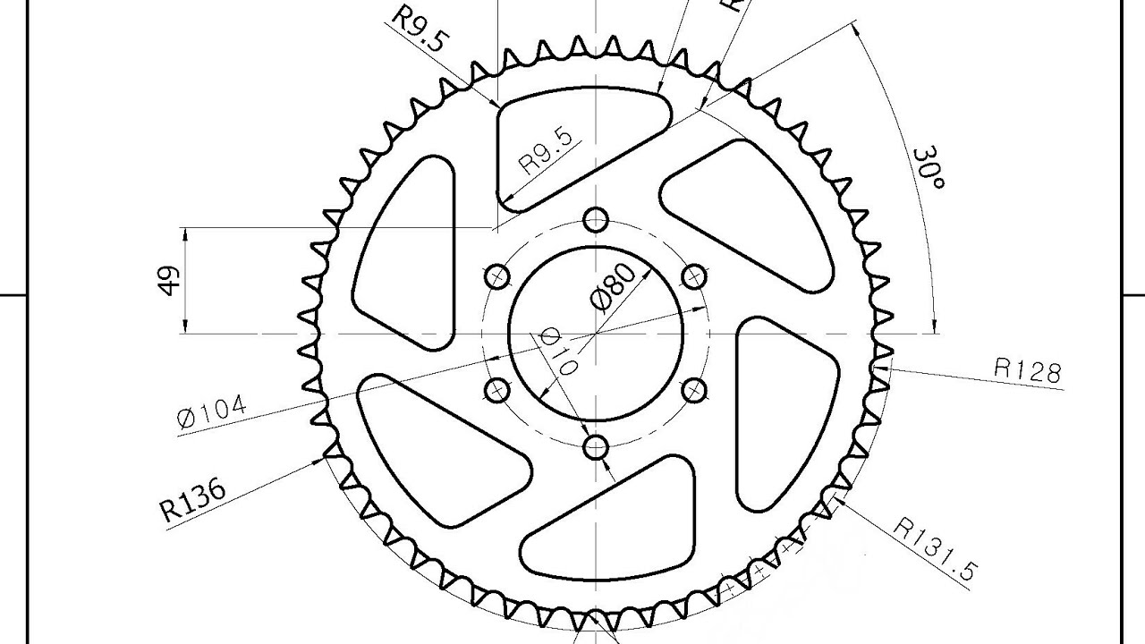
Autocad 2d Gear Practice Youtube

Pin On 3d Cad Exercises

Learn Autocad 2012 Video Tutorial How To Create A Toothed Gear Using Array Youtube
0 comments
Post a Comment